
A failed fluorescent troffer over an office workstation is rarely just a lamp problem. By the time a facility team replaces ballasts, tubes, and lenses, a full LED fixture upgrade is often the better maintenance decision. Knowing how to install LED troffers correctly helps protect the new equipment, maintain a clean ceiling line, and avoid electrical or support issues that can delay occupancy.
Most LED troffers are designed for suspended T-bar ceiling grids, especially common 2x2 and 2x4 openings. Installation is straightforward for a qualified electrician, but it is not simply a matter of setting a fixture into the grid. Fixture weight, branch-circuit voltage, dimming controls, emergency backup requirements, and local code all need to match the project before power is restored.
Confirm the Troffer and Ceiling Are Compatible
Start with the ceiling opening, not the old fixture label. Measure the grid opening and verify whether the project calls for a 2x2, 2x4, or less common size. A nominal 2x4 troffer is made to rest in a standard 2-foot by 4-foot T-bar opening. Do not assume the outside dimensions of a removed fixture tell the whole story, particularly in older ceilings with bent grid components or nonstandard framing.
Next, check the electrical specifications. Commercial LED troffers commonly operate on 120-277V, which suits many office, retail, school, and multi-use commercial circuits. Other models may have a narrower voltage range or require 347-480V service for certain larger facilities. The fixture voltage rating must match the available branch circuit.
Review the selected color temperature, wattage, and lumen package before installation. Many commercial models have field-selectable wattage and CCT switches behind the driver compartment cover. Set them before the fixture goes into the ceiling whenever possible. It is faster, and it reduces the chance of opening a finished ceiling later to correct a setting.
The installation method also depends on the product type. A new LED lay-in troffer replaces the entire fixture. An LED retrofit kit keeps the existing troffer housing and replaces internal components. A retrofit can make sense when housings are in good condition, and the approved kit is designed for that specific application. A full fixture replacement is often the cleaner option when old housings are corroded, damaged, poorly grounded, or fitted with aging ballasts.
Plan the Circuit, Controls, and Support
Before removing existing equipment, identify the circuit and determine how the new fixture will be controlled. A basic switched troffer needs line, neutral, and equipment grounding connections. A 0-10V dimming fixture also needs separate low-voltage dimming conductors, typically violet and gray or pink and gray depending on the driver. Keep dimming wiring separate from line-voltage conductors as required by the fixture instructions and applicable code.
If the space uses occupancy sensors, daylight harvesting, wireless controls, or a building automation system, confirm compatibility before installation. A dimmable LED troffer will not automatically work with every legacy control. An incompatible dimmer can cause flicker, limited dimming range, flashing, or driver failure.
Support deserves the same attention as wiring. The ceiling grid is typically intended to locate and carry the fixture within the ceiling plane, but it may not be the only required support. Follow the fixture instructions, the ceiling system requirements, and the authority having jurisdiction. Many installations require independent support wires or approved support methods connected to the structure above, especially where seismic provisions apply. Never rely on a damaged, loose, or overloaded grid.
Tools and Materials for LED Troffer Installation
The exact materials depend on the fixture and building conditions, but a typical commercial installation requires these items:
- Lockout/tagout equipment and a properly rated voltage tester
- Insulated hand tools, wire strippers, approved connectors, and electrical tape where needed
- Ladder or mobile platform rated for the working height
- Support wire, fasteners, and ceiling-grid accessories required by the fixture instructions
- Safety glasses, gloves, and replacement ceiling tiles if existing tiles are damaged
Have the fixture's installation sheet available at the work area. It identifies conductor connections, dimming leads, selectable settings, mounting requirements, and any restrictions related to damp locations, insulated ceilings, or emergency battery backup models.
How to Install LED Troffers Step by Step
1. De-energize and verify the circuit
Turn off the branch circuit at the panel and apply lockout/tagout procedures appropriate for the site. Do not depend on a wall switch alone. Use a properly rated tester to verify absence of voltage at the fixture junction box and supply conductors before touching any wiring.
If circuits are mislabeled, stop and identify the correct breaker. Shared neutrals, multiwire branch circuits, and emergency circuits require additional care. A qualified electrician should handle any condition that is unclear.
2. Remove the existing fixture carefully
Remove the existing fluorescent fixture, lamps, lens, and ballast components only after the circuit is confirmed de-energized. Support the old fixture while disconnecting wiring. Fluorescent lamps may contain mercury and must be handled and disposed of according to applicable requirements.
Inspect the branch-circuit conductors, junction box, grid, and nearby ceiling tiles. Replace damaged wire insulation, corroded connectors, broken grid tees, or stained tiles before putting a new LED fixture in place. An LED upgrade should not conceal existing electrical or water-intrusion problems.
3. Prepare the grid opening and independent supports
Clear the 2x2 or 2x4 opening and make sure the T-bar grid is square, level, and fully seated. If the fixture requires safety wires or independent support, install them now from approved structural attachment points above the ceiling. Do not attach support wires to sprinkler piping, conduit, ductwork, or other systems unless specifically permitted and engineered for that use.
For a row of troffers, check alignment across the room before setting every fixture. A ceiling grid that has shifted over time can make a straight fixture layout look uneven, even when each unit fits its opening.
4. Make electrical connections in the junction box
Open the LED troffer's access plate or junction box. Bring the supply conductors into the box through an approved knockout and connector. Connect the branch-circuit line conductor to the fixture's line lead, neutral to neutral, and equipment ground to the green grounding lead or grounding point.
Connect 0-10V dimming leads only when the control system calls for them. Cap unused dimming leads individually according to the manufacturer's instructions. Do not connect low-voltage control conductors to line voltage.
Make all splices with listed connectors sized for the conductor type and quantity. Tuck conductors into the junction box without pinching them, then reinstall the access cover securely. The wiring compartment must remain accessible as intended by the fixture design.
5. Set wattage, color temperature, and backup options
If the troffer has selectable wattage or color temperature, set the switches to the project specification before final placement. Higher wattage settings provide more light but increase connected load and may create glare in low-ceiling offices. Lower settings can reduce energy use and work well in corridors, conference rooms, and spaces with a dense fixture layout.
For emergency battery backup troffers, follow the manufacturer's sequence for connecting the battery and testing the indicator. These fixtures need an unswitched hot conductor so the battery can charge even when normal lighting is switched off. A switched-only feed will leave the emergency function unavailable when it is needed.
6. Set the fixture into the ceiling grid
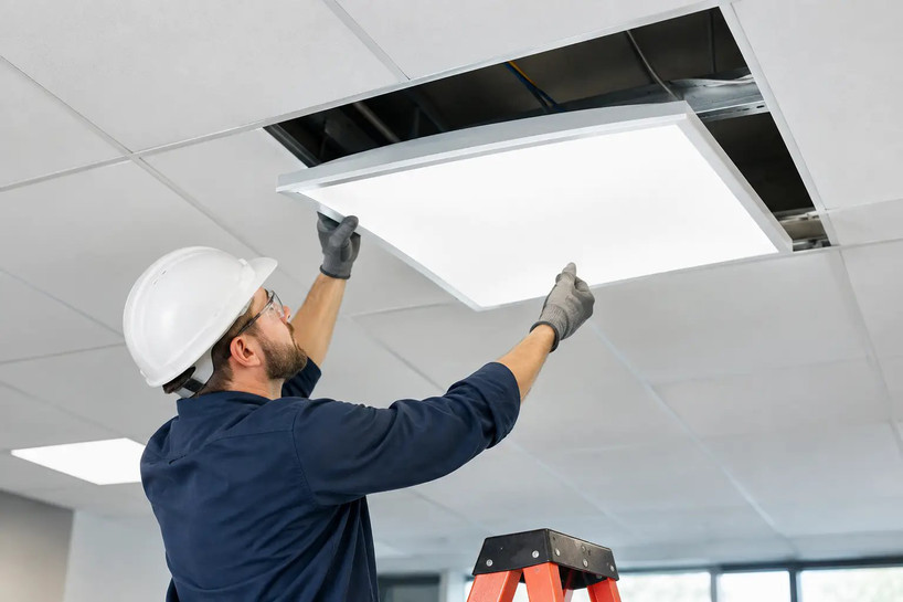
With a second installer supporting the fixture when necessary, lift the troffer through the grid opening at an angle and lower it until the flange rests evenly on the T-bars. Confirm that the fixture sits flat and does not rock, bow the grid, or leave gaps around the edges.
Attach any required support wires, seismic clips, or mounting brackets. Keep supply wiring and support wires clear of the LED lens, driver cover, and ceiling tiles. Reinstall or trim adjacent tiles only as needed to maintain a neat, supported ceiling plane.
7. Restore power and test performance
Remove tools and loose materials from the ceiling, restore the circuit, and test the fixture from its normal control point. Check for immediate startup, even illumination, correct color temperature, and proper dimming response. If several troffers are being installed, compare output across the area before demobilizing.
Test emergency backup units using the designated test switch and verify the charge indicator status. Document fixture locations, circuit numbers, wattage settings, CCT settings, and any control zones for future maintenance records.
Common LED Troffer Installation Problems
A troffer that will not turn on may have an open neutral, incorrect voltage, a loose connector, or a control-wire issue. If a dimmable fixture turns on but flickers, disconnecting the dimming input for a controlled test can help isolate whether the driver or control system is responsible. Follow the fixture instructions and use qualified personnel for live troubleshooting.
Uneven light across a room is often a specification issue rather than an installation defect. Mixing 3500K and 4000K settings, using different wattage selections, or combining new high-output troffers with old fluorescent fixtures can produce a visibly inconsistent result. Confirm settings before a large rollout, ideally by installing and reviewing a small sample area first.
A sagging grid or crooked fixture points to a ceiling-support problem. Do not force the troffer into a distorted opening or use the fixture body to straighten the grid. Repair the ceiling system and add required independent support before completing the installation.
When to Bring in an Electrical Contractor
A maintenance team may handle fixture swaps where permitted and properly qualified, but some projects call for an electrical contractor from the start. This includes new branch circuits, voltage changes, emergency lighting upgrades, extensive dimming controls, occupancy sensors, damaged wiring, and work in buildings with strict inspection requirements.
For multi-fixture upgrades, standardizing the troffer specification matters as much as the installation labor. Matching voltage, dimensions, driver type, lumen output, CCT, and control compatibility across the order reduces field surprises. Last Stop Lighting can help commercial buyers narrow those specifications before fixtures arrive on site.
A properly installed LED troffer should disappear into the ceiling visually while delivering reliable, even light for years. Take the extra time to verify the grid, circuit, controls, and support details before closing the ceiling, and the upgrade will be easier to maintain long after the installation crew leaves.