
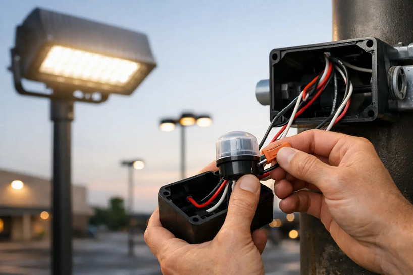
A parking-lot fixture that stays on all day or never turns on at dusk is often blamed on the LED driver. In many cases, the real issue is the control wiring. Knowing how to wire photocell controls correctly helps prevent wasted energy, premature component failures, and after-hours safety gaps around buildings, walkways, loading docks, and site entrances.
Photocells are straightforward devices, but commercial applications add variables: 120-277V versus 347-480V systems, switched versus unswitched feeds, LED driver inrush current, contactor-controlled lighting banks, and local electrical-code requirements. Use the control diagram supplied with the photocell and fixture as the final authority. Installation should be performed by a qualified electrician with the circuit de-energized and verified safe before work begins.
How to Wire Photocell Controls: Know the Circuit First
A standard line-voltage photocell senses ambient light and opens or closes an internal switching contact. At dusk, it closes the circuit to energize the fixture. At daylight, it opens the circuit to turn the fixture off.
Most hardwired photocells use three leads:
- Black is typically the incoming unswitched line or hot conductor.
- Red is typically the switched load conductor going to the fixture or lighting contactor.
- White is typically neutral.
That color convention is common, not universal. Verify the label, wiring diagram, voltage rating, and lead identification on the actual control before making connections. A photocell designed for 120-277V should not be installed on a 480V circuit, and a 347-480V control is not interchangeable with a lower-voltage model.
The photocell must receive an unswitched line feed. If it is connected downstream of a wall switch, time clock, or occupancy control that opens the hot conductor, the photocell cannot sense dusk and operate the lighting as intended. A separate control can still be used, but the control sequence must be planned deliberately.
Basic 120-277V wiring arrangement
For a typical single fixture or small fixture group on a 120-277V branch circuit, connect the branch-circuit hot to the photocell's black line lead. Connect the photocell's red load lead to the fixture's hot lead. Splice the branch-circuit neutral, photocell white neutral lead, and fixture neutral together. Connect equipment grounding conductors separately to the fixture housing and any required grounded metal enclosure.
In plain terms, the photocell switches the hot conductor only. Neutral remains continuous from the supply to the fixture. Do not use the photocell's white wire as an equipment ground, and do not omit the neutral if the control requires one.
The circuit should follow this basic path:
Supply hot -> photocell line -> photocell load -> fixture hot
Supply neutral -> photocell neutral + fixture neutral
Equipment ground -> fixture ground / enclosure ground
Use listed connectors, properly sized conductors, weather-rated enclosures, and strain relief where required. On exterior poles, wall packs, canopy lights, and flood lights, moisture protection at the splice point matters as much as the conductor connections.
Check Voltage, Load, and LED Inrush Before Installation
A photocell is a switching device, not a universal answer for every lighting circuit. Match it to the electrical system and the load it will control.
Start by confirming the supply voltage with an appropriate meter. Many commercial LED area lights, wall packs, and flood lights are rated 120-277V, which allows the same fixture to operate on 120V, 208V, 240V, or 277V systems. The photocell must carry a matching multi-voltage rating. If the project uses 347V or 480V distribution, select a control specifically listed for that voltage.
Next, check the control's load rating. LED fixtures draw less steady-state current than older HID lighting, but their drivers can create a high momentary inrush current at startup. A photocell that appears adequately rated based on fixture wattage alone may have a shortened life when switching a large bank of LED fixtures directly.
For a few fixtures, a properly rated photocell may switch the load directly. For a larger parking lot, exterior building perimeter, or multi-pole site-lighting circuit, the better design is often a photocell controlling a lighting contactor. The photocell then switches the contactor coil, while the contactor handles the fixture load. This reduces stress on the photocell and makes the system easier to expand or service.
It depends on the equipment. Check the photocell's tungsten, ballast, LED, and motor ratings, plus its maximum inrush specification if provided. Review the fixture driver's input current and inrush data. When specifications are unclear, size the control conservatively or use a contactor-based design.
Wiring a Photocell to a Lighting Contactor
A contactor arrangement is common where one control operates multiple luminaires. Instead of routing all fixture current through the photocell, the photocell energizes the contactor coil at dusk.
The exact wiring depends on the coil voltage and whether the contactor uses a neutral-referenced coil or a line-to-line coil. A 120V coil generally needs hot and neutral. A 277V coil generally uses 277V hot and neutral. A 208V or 240V coil may be connected line-to-line and may not use neutral at all.
For a neutral-referenced coil, the usual arrangement is to connect the unswitched control hot to the photocell black lead, connect the photocell red lead to one coil terminal, and connect the other coil terminal to neutral. The photocell white lead connects to neutral as required by its design. The lighting branch conductors are then switched by the contactor's power poles.
Do not assume a photocell can switch any coil. Confirm the control's voltage rating and its permitted ballast, LED, or inductive load rating. An electrician should also verify that the contactor is properly rated for the supply voltage, pole count, fixture load, and available fault current.
Mount the Sensor Where It Reads Real Daylight
Correct wiring cannot overcome poor sensor placement. The photocell lens needs a clear view of ambient daylight, but it should not face a fixture's direct light output. If fixture light reaches the sensor, the control can cycle on and off after dark, a condition commonly called false switching or cycling.
On a pole-mounted area light, mount the photocell so the lens faces away from the primary distribution of the luminaire when the fixture design allows it. On wall packs and flood lights, avoid locations where reflected light from a light-colored wall, canopy, or nearby sign shines into the sensor. Keep the control away from heavy shade caused by building overhangs, trees, or architectural screens, which can make lights turn on earlier than necessary.
For twist-lock photocells, confirm that the receptacle is oriented correctly and that the gasket seats fully. A loose or poorly sealed control can admit moisture, corrode contacts, and cause intermittent operation. Use a locking receptacle and photocell with compatible ANSI-style configuration where applicable.
Test the Installation Without Creating a Daytime Problem
After restoring power, allow the photocell time to respond. Many controls include a delay of 30 seconds to several minutes so headlights, lightning, and passing shadows do not cause nuisance switching.
To test a daylight-responsive photocell, cover the lens completely with opaque material. Do not use a partially transparent hand or light-colored tape that still allows enough light to reach the sensor. Wait through the control's stated delay, then confirm that the fixture or contactor energizes. Remove the cover and allow the control to return to daylight mode.
If the lights do not operate, begin with voltage checks. Verify unswitched line voltage at the photocell input, then verify switched voltage at the red load lead after the lens is covered. If line voltage is present but no switched output appears after the delay, the control may be miswired, incorrectly rated, obstructed, or defective. If switched output is present but the fixture remains off, inspect the downstream circuit, driver, neutral connection, breaker, and contactor coil or power poles.
Avoid the Failures That Create Repeat Service Calls
The most common wiring error is reversing the black line and red load conductors. The fixture may behave unpredictably, remain energized, or fail to switch correctly. Another frequent problem is feeding the photocell from a switched source instead of a constant hot conductor.
Neutral mistakes are equally costly. A control that requires neutral will not operate correctly without it, and a loose neutral can produce intermittent behavior that looks like a bad driver or failed photocell. On multiwire or shared-neutral circuits, make sure the design and disconnecting means comply with applicable code requirements.
Also avoid installing a photocell where it sees its own fixture light, exceeding its load rating, using an indoor-only enclosure outdoors, or selecting a control with the wrong voltage range. For replacement work, document the existing supply voltage and fixture count before ordering. A matching physical receptacle does not prove the electrical rating is correct.
For commercial exterior lighting, the right photocell is part of the system specification, not an afterthought. Match the voltage, switching method, mounting style, and load rating to the fixture layout, then test the circuit before the crew leaves the site. That approach keeps lights operating when the property needs them and keeps avoidable maintenance calls off the schedule.